How To Fix “Abutment Top Cap Angle Violated” Error in 3shape

How To Fix “Abutment Top Cap Angle Violated” Error in 3shape

Summary: Over in the Facebook 3shape Study Group, we get this question weekly, if not more often, about how to fix this “Abutment Top Cap Angle Violated” error in 3shape. This guide was originally written by Sevan Pulurian and I thought it had some really great info so I wanted to feature it on this blog.

Huge thank you to the 3shape Study Group and everyone who makes the online 3shape community such a great one to be a part of!

If you are designing any implant restoration in 3shape, then there could be chances that you have received the error message “Abutment Top Cap Angle Violated” when trying to finalize your design.

We see this question come up on a weekly basis and there are lots of 3shape users out there who receive this message.

Solution to Fix Abutment Top Cap Angle Violated in 3shape:

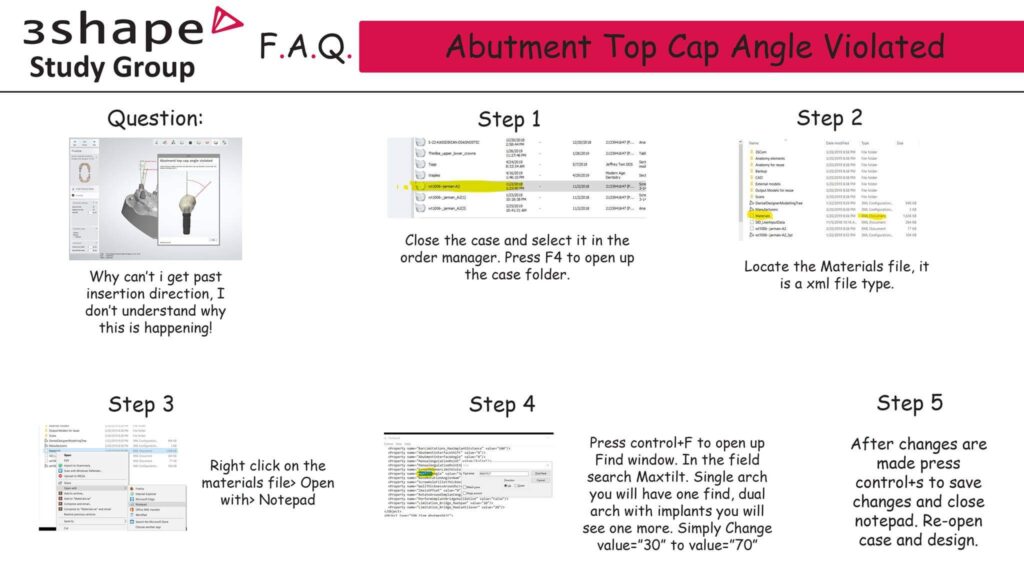
Alright! Now let’s take a look at how we solve this issue. Just follow the steps below or the ones found in the infographic above and you’ll be well on your way.

Note: This solution involves modifying material files and may corrupt your order and make it unusable if not properly edited. We take no responsibility for any problems this may cause to your dental system and it is advisable to make a backup of your order before proceeding

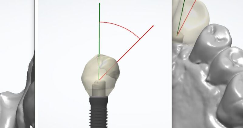
Step 1: Firstly you’ll see an error saying Abutment Top Cap Angle Violated

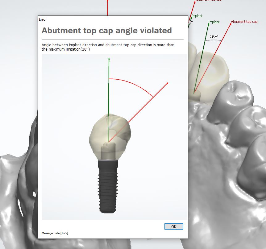
Error: Angle between implant direction and abutment top cap direction is more than the maximum limitation (30°) Message code [1:25]

This generally happens because there’s an error with how the implant insertion direction detects the transformation during the design. No actual limitation has been violated.

Step 2: Close The Case and Explore in Windows

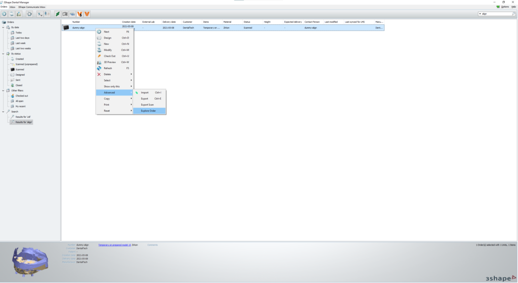
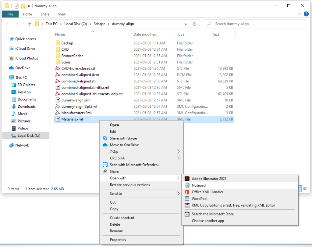
You’re going to want to close the case, save the design to speed up the redesign process later if you’re prompted to do so. Once the case is closed, go to Dental Manager and highlight the case, right click and advanced > explore order, or simply press F4 on the keyboard as a shortcut to open the case folder in Windows Explorer

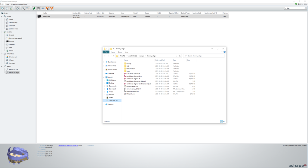
Step 3: Locate & Open Materials.xml File

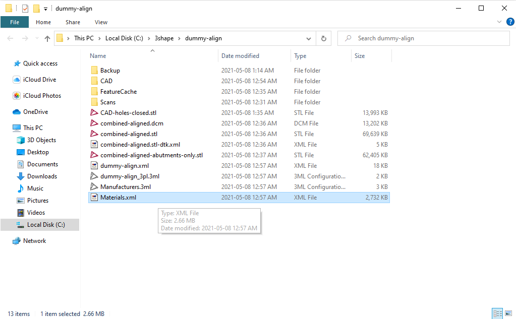
Locate the Materials.xml file in the Explorer folder and right click on the materials file > Open With > Notepad. (Alternatively you can use a dedicated xml editor, the one I use is XML Copy Editor)

Step 4: Edit Materials.xml File

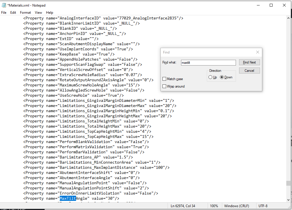
In Notepad, press ctrl+f to open up the search dialog box. In the search field type Maxtilt and press enter. (Note: For a simple single implant case, you will have one result, for multiple abutments or multiple arches, you will have multiple results that you will need to modify). Once the result is found, simply change the value from “30” to “70”

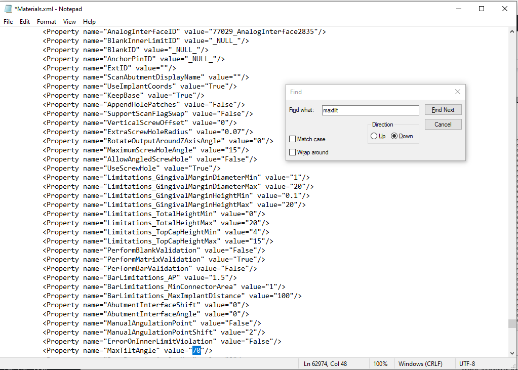
After the changes have been made, go to file > save, or hit ctrl+s to save your changes and close notepad.

Finally, re-open the case and proceed with the design!

Problem Solved!

About Minh Tran

minh_400w_jpg

Minh Tran is a 2nd generation dental technician from Windsor, Ontario, Canada. With 15+ years of experience, primarily as a CAD/CAM dental technician, Minh was one of the first users of 3shape Dental System in Canada and brings a wealth of knowledge. He is a lecturer, trainer, and has been a speaker, consultant, and technical advisor for multiple companies including 3shape, Asiga, core3dcentres North America, Fullcontour, Pritidenta, DAL, Medentika, and Abutment Direct.

Minh has served on the program advisory committee of St. Clair College in his hometown of Windsor to develop a new Dental Laboratory Technology program. Minh is a member of the American Prosthodontic Society and currently serves on the communications committee. He is also the founder and creative director of DentalTechTips, an online independent publication and blog focusing on unbiased product reviews, offering tips, tricks, tutorials, and the latest and greatest in the dental laboratory industry.

Millbox Tips and Tricks: Part 1 –  With Evan Katz

Millbox Tips and Tricks: Part 1 – With Evan Katz

Hey, whats up guys! Today we’ve got a special post for you. This article was written by Evan Katz and I thought it had some really great info so I reached out to see if we could feature it on this blog.

Huge thank you to Evan and the team over @Argen Canada for letting us share it with our readers!

Evan Katz RDT, Senior Education & Product Development Manager at Argen Canada Evan is an RDT and Technical Specialist/Trainer in all aspects of CAD/CAM workflow, including Intraoral software and hardware, CAD design, CAM strategy & mill repair.

Understanding how CAM software fully functions can take some time.
In most cases, it also helps to fully understand how your CAD software works. In the day-to-day rush of having to scan, design mill, sinter and finish so many cases, we sometimes forget that the software we use (either CAD or CAM) can often help us out by allowing us to become more efficient, but mainly more consistent.

Argen sells, services and supports Roland mills – these dental mills come with MillBox software, developed by Lab and CIMsystems SRL. As of 2017, we only sell MillBox, which runs Sum3D in the background. Updating your Sum3D licence to MillBox is quite easy!
MillBox offers a number of under-utilized tools that can help you become more effective such as:

  • Internal cavity adjustment
  • Screw access hole adjustment
  • Importing contact area data **SNEAK PEEK**

Internal Cavity Adjustment:

When you design an abutment or a screw-retained crown from a scan body (library abutment), we do not have any control over the spacer between the titanium base and the internal aspect of the abutment/crown. This can lead to a loose fit which will result in too much rotation between the titanium base and the part. This can be somewhat counterbalanced by cementing the base to the part and using the contact areas as rotational stops, however with MillBox this can be controlled.The spacing within internal cavity can be adjusted very easily.

Simply enable the abutment/crown by clicking onto it – then click the Tools option:

Now open the Cavity Fit option within the sub-menu, which in-turn open the Adjust Cavity Fit menu

You can now make changes to the internal cavity, either using the positive numbers (+) to make a tighter fit, or use the negative number (-) to make a looser fit. Once you have decided how loose or tight you want to make the part, by clicking the check mark the internal cavity will turn the color associated with the value.

Keep in mind this will not change the .STL, it simply adds or removes the specified amount from the milling parameters

Screw-Access Hole Adjustment:

If you are not using a scan body to create a screw retained abutment or crown, you will likely be manually placing the hole into your crown through your CAD.
In some cases, the diameter of the screw access hole cannot be adjusted in CAD and you will be left with either a hole that is too small or too large. Both situations will require some post-processing work which can be done using MillBox CAM. This can be done for both library and non-library abutments.

Within MillBox, you have the ability to adjust the diameter of the screw-access hole, as well as the plunge depth. In this case, we will concentrate on the screw-access hole diameter.

After the .STL has been imported, click the Tools button on the left side of the software.
Once the Tools options are open, click the Curves and Surfaces icon to open up that specific operation.
Once this has been opened, a list of specific operations will open on the top banner area.
When clicking Change Cylinder Size, your .STL will disappear and only the milling curves will be present.

On the screw-access hole curve you will see 2 gold dots. By clicking on a dot, it will open up a graphic that shows the diameter of the hole. This can be changed to make it smaller or larger all depending on your situation.

Again, this will not affect your .STL, it just adds a milling offset to the hole milling operation.

Importing Contact Area Data **SNEAK PEEK**

In an upcoming version of Argen MillBox, you will be able to export your contact areas that you have created in 3Shape CAD. Millbox will be able to recognize this as a contact and avoid placing support pins onto that area.

MillBox is a very powerful tool which if used correctly will help your laboratory gain superior and consistent milling results. Putting a lot of effort and time into your CAD design only to have less than ideal milling results is frustrating and often leads to additional post-processing time.

Let the CAD and the CAM work for you!

About Argen

For more than 50 years Argen, a family-owned American company and partner to dental labs worldwide, has served the dental industry and continues to invest in new and innovative product offerings to provide dental labs with affordable, high-performance products and industry-leading customer service. Argen.com